Arduino STM32druino
关键字:Arduino、Nucleo-64、STM32F103RB
 |
|---|
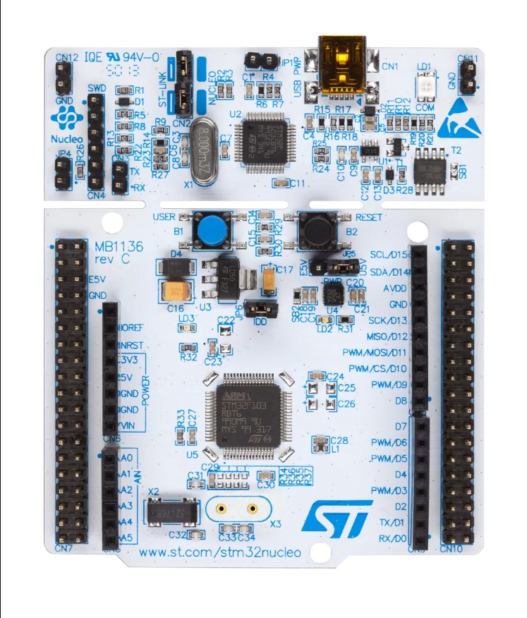
| 板子图片 |
 |
 |
 |
|---|---|---|
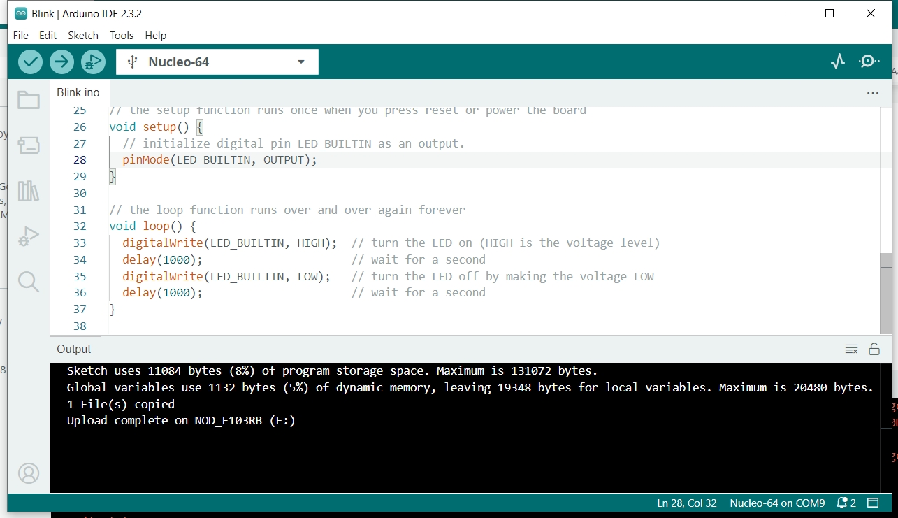
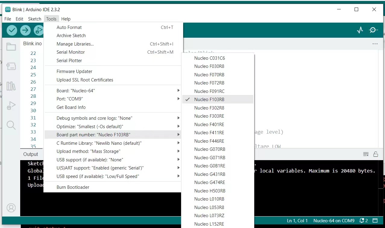
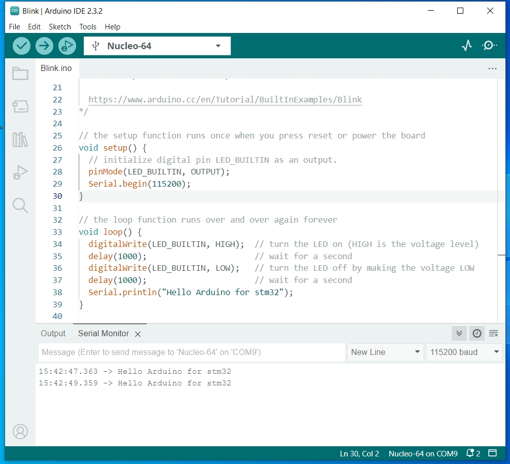
| HelloWorld点灯 | 注意配置-F103RB | 显示效果 |
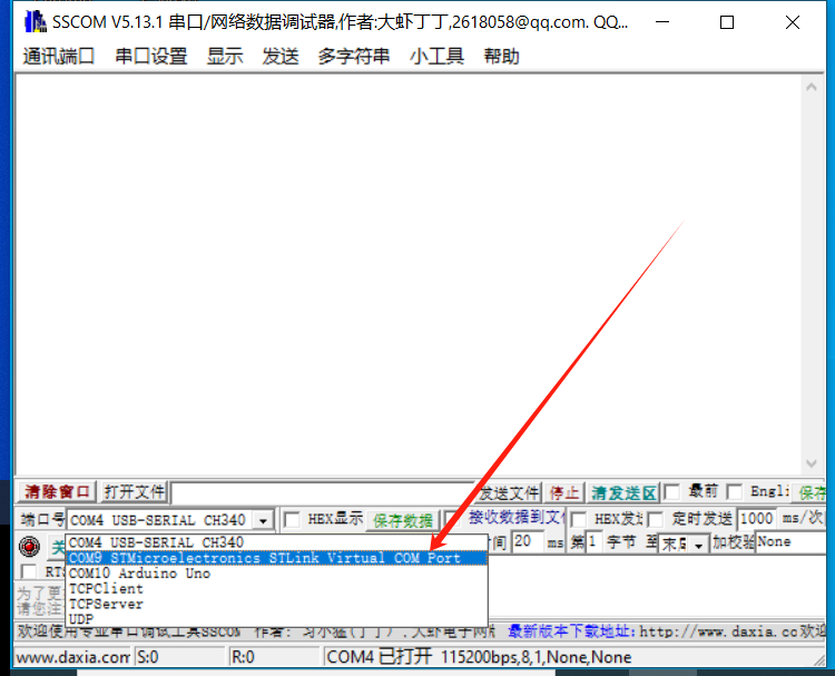
默认调试串口是STLink虚拟的,使用串口助手连接“默认的D1D0”是接收到不数据的,因为那是Serial2。
 |
 |
|---|---|
| 串口Demo | 串口名字 |
PINOUT
 |
 |
|---|---|
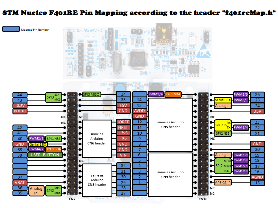
| Arduino风格管脚 | 外围引脚 |
 |
|---|
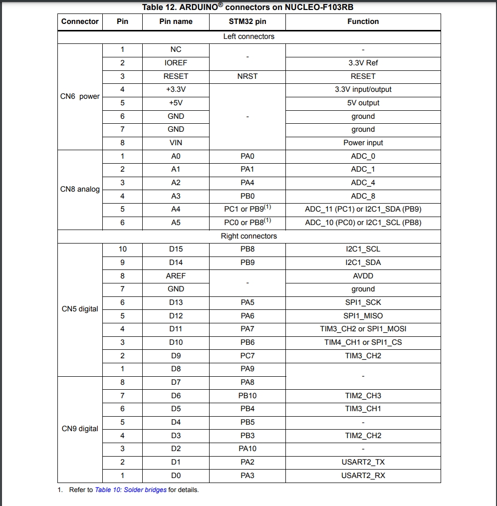
| 数据手册中管脚对应图 |
补充配置电路板
https://github.com/stm32duino/BoardManagerFiles/raw/main/package_stmicroelectronics_index.json
更多参考资料: https://os.mbed.com/platforms/ST-Nucleo-F103RB/
For STM32F103C8T6 board, the default Serial is actually mapped to the 2nd serial port of the chip. This port is wired to the on-board ST-link. You can then plug your PC to the USB-port of the ST-link and get Serial Monitor on Arduino IDE right away.
来自:https://www.stm32duino.com/viewtopic.php?t=1354
串口1
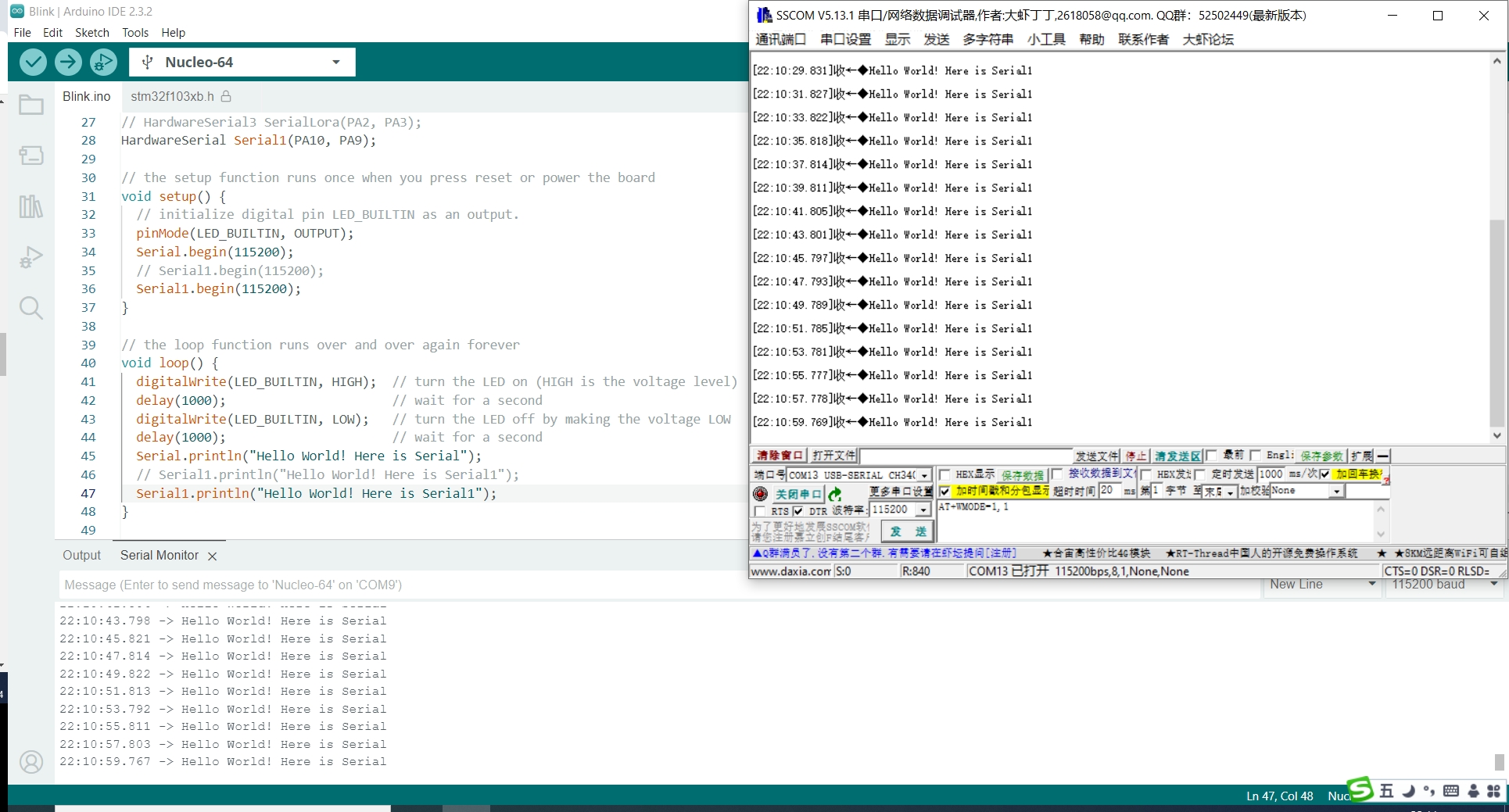 |
|---|
| Serial1的使用 |
/*
HardwareSerial Serial1(PA10, PA9);

// the setup function runs once when you press reset or power the board
void setup() {
  // initialize digital pin LED_BUILTIN as an output.
  pinMode(LED_BUILTIN, OUTPUT);
  Serial.begin(115200);
  // Serial1.begin(115200);
  Serial1.begin(115200);
}

// the loop function runs over and over again forever
void loop() {
  digitalWrite(LED_BUILTIN, HIGH);  // turn the LED on (HIGH is the voltage level)
  delay(1000);                      // wait for a second
  digitalWrite(LED_BUILTIN, LOW);   // turn the LED off by making the voltage LOW
  delay(1000);                      // wait for a second
  Serial.println("Hello World! Here is Serial");
  // Serial1.println("Hello World! Here is Serial1");
  Serial1.println("Hello World! Here is Serial1");
}
资源配置
默认D0、D1不可用,需要按照如下图所示:
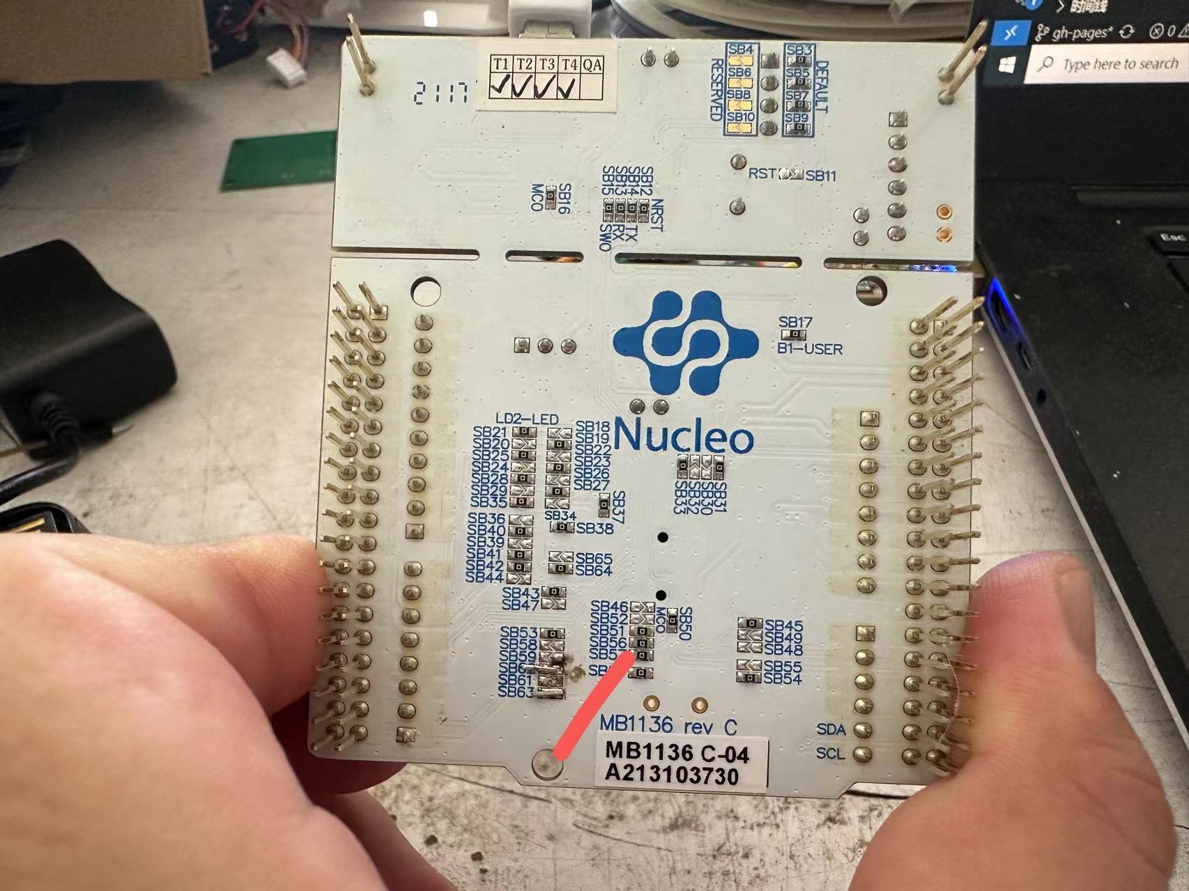 |
|---|
| 修复D0 D1不可用问题 |